Thursday, 14 March 2013

Virtualised Exalogic and its use of Infiniband Partitions

Introduction

Right from the outset of Exalogic it has depended heavily on the Infiniband network interconnect to link all the components together.  With the release of the virtualised Exalogic and all the multi-tenancy features the flexibility of the Infiniband fabric to provide secure networking is critical.  This posting is an attempt to explain some of the underlying operations of the Infiniband network and how it provides secure networking capability.

Infiniband Partitions

When thinking about how we can keep virtual servers (or vServers which equate to the guest operating systems) isolated from each other there is often a statement made that Infiniband Partitions are analogous to VLANs in the Ethernet world.  This analogy is a good one although the underpinnings of Infiniband (IB) is very different from the Ethernet routings.

An IB fabric will consist of a number of switches, these can either be Spine switches or Leaf switches, a spine switch being one that connects switches together and a leaf being one that connects to hosts.  On a standalone Exalogic or a smaller Exalogic cabled together with an Exadata then we can link all the compute nodes, storage heads/Exadata storage cells together via leaf nodes only.  In each physical component or host that is connected to the fabric is a dual ported Host Channel Adapter (HCA) card that allows cabling from the host to multiple switches. i.e. there are two architectural deployment diagrams that are possible, as shown below:-


Simple topology - 1 level only
Spine Switch topologies - 2 Levels
In both of these cases a "Fat Tree" or "Clos" topology is followed, this simply means that there are more physical cables connecting the switches together so that there is additional bandwidth/capacity on the busier logical links.  In the above diagrams the "host" could be a compute node or storage component.

When we create an IB partition what we are doing is instructing the fabric about which hosts can communicate with other hosts in the fabric over that particular partition.  There are a couple of very simple rules to an Infiniband fabric:-
  • A full member can communicate with all members of the partition
  • A limited member can only communicate with a full member of the partition
Using these rules we can create multiple partitions to build up the appropriate visibility.   So for example suppose we are using an exalogic and are deploying App A to hosts 1 & 2 and App B to hosts 3 & 4 but both applications had a need to access a shared service App C that is located on hosts 5 & 6 then we might have partitions setup as shown below.

A Simple Partitioning example

In this case Hosts 1 & 2 are both full members of partition 1 so app A can talk to both instances.  Partition 2 hosts 3 & 4 as full members for App B.  Then Partition 3 has hosts 5 & 6 as full members and Hosts 1-4 as limited members, in this way both applications A & B are able to access the services of App C but using partition 3 it is impossible for App A to have any access to App B.


Virtualised Exalogic and Partitions

Now we have an idea of what a partition does lets dive into the details of a virtualised exalogic and consider just how we can create multiple vServers and maintain network isolation between them.  We will do this by considering an example topology consisting of two applications each deployed in a 3 tier topology although we will not concentrate much on the DB tier in this blog posting.  The first tier being a load balancing "Oracle Traffic Director" set of instances, then an application tier with multiple WebLogic server instances and below that a database tier.   The diagram below shows the sort of Exalogic deployment we will consider.  Database tier omitted for simplicity.

Application Deployments on a virtualised Exalogic

So in this case the client population is split on different tagged VLANS -  Application A using VLAN 100 and Application B using VLAN 101.  Both of these VLANS are connected to different "Ethernet over Infiniband" or EoIB networks on the Exalogic rack where two partitions are created with each partition including the special Ethernet "Bridge"  ports on the Exalogic gateway switches.  Internally each set of vServers is also connected to another private network which is implemented as another IB partition.  Should the vServers need access to the ZFS Storage appliance that is held within the Exalogic rack then they are connected to the storage network.  The storage network is a special one created on installation of the rack, any connected vServers are limited members with just the storage appliance as a full member, in this way there is no way to connect between vServers on this network.

Now think about the switch setup for each of these networks and how the data is transmitted.


Ethernet over Infiniband Networks (EoIB connecting to vLAN tagged external network.)


These networks can be created as described in the "tea break snippets" what we will concentrate on is what is happening behind the scenes and use some of the Infiniband commands to investigate further.  If we consider the connection to the Ethernet VLAN 100 then we can investigate just how the partition has been setup, firstly using the showvnics command to identify the external NICs that are in use and then using the smpartition list active to pick out the partition setup.


[root@<gw name> ~]# showvnics | grep UP | grep 100
ID  STATE     FLG IOA_GUID                NODE                        IID  MAC               VLN PKEY   GW
--- --------  --- ----------------------- --------------------------- ---- ----------------- --- ----   --------
  4 UP          N A5960EE97D134323        <CN name> EL-C <cn IP>      0000 00:14:4F:F8:69:5D 100 800a   0A-ETH-1
 38 UP          N 4A282D7AEEF49768       
<CN name> EL-C <cn IP>      0000 00:14:4F:FB:34:19 100 800a   0A-ETH-1
 48 UP          N 0C525ADA561F7179       
<CN name> EL-C <cn IP>      0000 00:14:4F:FB:22:14 100 800a   0A-ETH-1
 49 UP          N F9E4DC33D70A0DA2       
<CN name> EL-C <cn IP>      0000 00:14:4F:F8:BE:1F 100 800a   0A-ETH-1
 30 UP          N AE82EFAD4B2425C7       
<CN name> EL-C <cn IP>      0000 00:14:4F:F8:55:58 100 800a   0A-ETH-1
 25 UP          N 73BDD3B88EE8CFE1       
<CN name> EL-C <cn IP>      0000 00:14:4F:F9:FA:01 100 800a   0A-ETH-1
 50 UP          N CC5301F73630E6EA       
<CN name> EL-C <cn IP>      0000 00:14:4F:F9:5A:85 100 800a   0A-ETH-1
 28 UP          N D2B7E3F14328A5F6       
<CN name> EL-C <cn IP>      0000 00:14:4F:FA:66:7E 100 800a   0A-ETH-1
 29 UP          N 31E36AB07CFE81FB       
<CN name> EL-C <cn IP>      0000 00:14:4F:FB:5B:45 100 800a   0A-ETH-1

#
Display of virtual Network Interface Cards on IB network

We are seeing the virtual NICs that are configured for VLAN 100 on the switch, in this example we have 9 vNICs operational and they are using the partition identified by the hex number 800a.  (In my test environment there are more vServers than shown in the architecture diagrams above.)  The IOA GUID is reflected on the vServer that is associated with the specific vNIC, this can be shown using the mlx4_vnic_info command on the vServer, with the ethernet NIC matched by the MAC or HWaddr.

[root@<My vServer> ~]# ifconfig eth166_1.100
eth166_1.100 Link encap:Ethernet  HWaddr 00:14:4F:FB:22:14 
          UP BROADCAST RUNNING SLAVE MULTICAST  MTU:1500  Metric:1
          RX packets:514101 errors:0 dropped:0 overruns:0 frame:0
          TX packets:52307 errors:0 dropped:0 overruns:0 carrier:0
          collisions:0 txqueuelen:1000
          RX bytes:769667118 (734.0 MiB)  TX bytes:9041716 (8.6 MiB)


#[root@<My vServer> ~]# mlx4_vnic_info  -i eth166_1.100 | grep -e IOA
IOA_PORT      mlx4_0:1
IOA_NAME      localhost HCA-1-P1
IOA_LID       0x0040
IOA_GUID      0c:52:5a:da:56:1f:71:79
IOA_LOG_LINK  up
IOA_PHY_LINK  active
IOA_MTU       2048
Matching GUID of VNIC to GUID in the vServer

We now can consider the actual partition.

[root@<gateway 1> ~]# smpartition list active
...
  = 0x800a:
0x0021280001a16917=both,
0x0021280001a1809f=both,
0x0021280001a180a0=both,
0x0021280001a17f23=both,
0x0021280001a17f24=both,
0x0021280001a1788f=both,
0x0021280001a1789b=both,
0x0021280001a1716c=both,
0x0021280001a1789c=both,
0x0021280001a1716b=both,
0x0021280001a17890=both,
0x0021280001a17d3c=both,

0x0021280001a17d3b=both,
0x0021280001a17717=both,
0x0021280001a16918=both,
0x0021280001a17718=both,
0x002128c00b7ac042=full,
0x002128c00b7ac041=full,
0x002128bea5fac002=full,
0x002128bea5fac001=full,
0x002128bea5fac041=full,
0x002128bea5fac042=full,
0x002128c00b7ac001=full,
0x002128c00b7ac002=full;
...


Partition Membership for partition 800a

What we can see here is that the partition includes 16 port GUIDs that have membership of "both" and a further 8 port GUIDs that are full members.  (IB partition membership of both is an Oracle value add to infiniband to allow vServers to be given either full or limited partition membership.)

What I can surmise from this output is that we are dealing with a 1/4 rack, I know this because there are 16 entries with both membership, each physical compute node is dual ported so has two entries in the partition.    We can match the GUID to the physical channel adapter (CA) by running the ibstat command on the compute node.

[root@el2dcn07 ~]# ibstat
CA 'mlx4_0'
        CA type: MT26428
        Number of ports: 2
        Firmware version: 2.9.1000
        Hardware version: b0
        Node GUID: 0x0021280001a17d3a
        System image GUID: 0x0021280001a17d3d
        Port 1:
                State: Active
                Physical state: LinkUp
                Rate: 40
                Base lid: 64
                LMC: 0
                SM lid: 57
                Capability mask: 0x02510868
                Port GUID: 0x0021280001a17d3b
                Link layer: IB
        Port 2:
                State: Active
                Physical state: LinkUp
                Rate: 40
                Base lid: 65
                LMC: 0
                SM lid: 57
                Capability mask: 0x02510868
                Port GUID: 0x0021280001a17d3c
                Link layer: IB
Infiniband port information on a compute node

There are also the 8 full member entries.  These relate to the Ethernet bridge technology of the Infiniband gateway switch.  Each switch has two physical ports that allow Ethernet connectivity to the external datacentre and each port is viewed as a dual ported channel adapter, hence each IB switch has four adapter GUIDs or 8 for the pair of gateway switches.

For a virtual Exalogic partitions are enforced at the end points - in the ports of the host channel adapter.  The partition plays no part in the routing of traffic through the fabric which is manged by the subnet manager, using the local Identifiers (LIDs).  Thus traffic linked to a particular partition can be routed anywhere in the fabric.  It is possible to use Infiniband such that each switch maintains a partition table then the switch can inspect the packet headers to match the P-Key in the header and enforce that only packets matching to entries in the partition table are allowed through.  This is not done for a virtual Exalogic.

Each HCA has two ports and each port maintains its own partition table which is updated by the subnet manager with all the partition keys that are accessible by that HCA.  Thus when a packet comes in the pKey of the header is matched to the local partition table and if no match found then the packet is dropped.  So in our example we can see that the partition handling traffic from the external world is effectively allowed to travel to every compute node.  This is necessary because the vServer may migrate from physical compute node to compute node and must still be able to communicate with the external world.   However how does this help with security and multi-tenancy if traffic can flow to every node?

The answer is that the isolation is solved at a different level.  Each vServer gets allocated a virtual function within the HCA.  The diagram below shows how the physical HCA can create multiple virtual functions  (up to 63) that are then allocated to each virtual machine.  This is also the mechanism that provides single root IO virtualisation (SR-IOV) for the optimal performance with flexibility.


From the fabric perspective partitioning is always setup at the physical level. There is one physical partition table per port of the HCA, and Subnet Manager updates this table with pKeys of partitions that are accessible by that HCA. So when packet comes in, the pKey in its header is matched with partition table of the physical port receiving the packet, and if no match is found the packet is dropped.  In a virtual Exalogic all compute nodes in the Exalogic are in the partition so traffic is never rejected via this route, unless it has been directed at the storage or another IB connected device such as an Exadata.

So what about isolation for Virtual Machines?   Each Virtual Function (pcie function) has its own virtual partition table,  this table is not visible or programmed by the Subnet Manager but is by the Dom0 driver. The partition table carries an index of the entries in the physical partition table that are accessible for each virtual function.  i.e. a mapping of partitions in the Infiniband network to specific vServers running on the compute node.

Enforcement is achieved by using the inifiniband construct of a queue pair (QP).  Queue pairs consist of a pair of send and receive queues that are used by software to communicate between hardware nodes.  Each HCA can support millions of QPs and each QP belongs to a pcie function (either a physical function or a virtual function).  Assignment is performed by the Dom0 driver on creation of a QP.  Each QP can only belong to one partition so when Dom0 creates a queue pair for a vServer on a specific partition it will use a virtual partition table of the VF to ensure this QP can be created.  When the QP recieves a packet it checks that the PKey in the packet header matches the pKey that is assigned to the QP.

Or to put it another way, when a virtual machine is started up on a compute node then the configuration of the guest VM interacts with the hypervisor to ensure that the QPs for the guest VM will only be for partitions that it is allowed to communicate over.  The allowed partitions defined in the vServers vm.cfg file.


Conclusion

By using Infiniband partitions and the Exalogic "secret sauce" in the virtualised Exalogic we setup secure communication paths where the IB fabric and HCA ensure that traffic on a particular partition can only communicate with the Exalogic Compute Nodes in the environment, then the hypervisor and HCA work in conjunction with each other to ensure that each vServer only has access to the specific partitions that have been administratively allocated to it.
In this way it is possible to maintain complete network isolation from each vServer while making use of a shared physical infrastructure.

Wednesday, 27 February 2013

Starting/Restarting the Exalogic Control Stack

Introduction

The installation process for a virtualised Exalogic will install a number of vServers that run the Exalogic Control cloud management stack.  Once installed this will generally be left up and running so that the virtual data centre can be administered.  However at times it may be necessary to stop/restart the control stack.  For example, if you want to backup the control vServers the simplest mechanism is to stop the instances and use the snapshot capability of the ZFS storage appliance.

This blog post provides some instructions on how to shutdown/restart the control stack.  This relates to the Exalogic 2.0.1 and 2.0.4 releases.  For the 2.0.6 release see the comments for this posting.  The same principles apply but the services are simpler to use or the lifecycle tool exaBR can be used to shutdown the control stack.  (exabr -r <repository path> stop control-stack )

Shutdown/Startup of Exalogic Control Software Stack

Exalogic Control consists of a number of different applications deployed to multiple vServers.
  • Enterprise Manager Ops Center (EMOC)
    • The main interface used for Exalogic Control to manage the Rack and Virtual Data centre.
  • Ops Center Proxy Controller
    • There are two proxy servers deployed.  Requests to manage the environment are sent from the EMOC server to one or other proxy server which issues the commands.  The Proxy servers are part of the architecture that enables Ops Centre to manage complex network topologies where the central EMOC server is not in the same network as  the servers that it manages or to allow requests to be load balanced between multiple proxies.
    • For Exalogic there are two proxies because some of the commands are issued to the compute node ILOMs.  A compute node cannot manage its own ILOM so it is necessary to have the two proxies deployed so that all compute nodes can be fully managed.
  • Oracle VM Manager (OVMM)
    • Used by EMOC to manage the virtual environment.
  • Oracle Database
    • Both EMOC and OVMM have a need for an underlying database to store configuration and state management into.
The software on these servers can be started and stopped independently of the vServer itself.  Each application has a slightly different start and stop command as shown below:-
  • EMOC 
    • Stop - /opt/sun/xvmoc/bin/satadm stop -w
    • Start - /opt/sun/xvmoc/bin/satadm start -w
  • Proxies 
    • Stop - /opt/sun/xvmoc/bin/proxyadm stop -w
    • Start - /opt/sun/xvmoc/bin/proxyadm start -w
  • OVMM
    • Stop - service ovmm stop
    • Start - service ovmm start
  • Database
    • Stop - service oracle-db stop
    • Start - service oracle-db start
To run these commands it is necessary to log onto each of the vServers in turn to run the command.  The order in which they should be run is:-
  • Start
    • Database
    • OVMM
    • EMOC
    • Proxy Server 1
    • Proxy Server 2
  • Stop
    • Reverse of start order.
 The simplest mechanism to access all these vServers is to ssh onto a compute node and then make use of the private IP addresses they have in the IPoIB-admin network.  (Probably 192.168.20.nn)  The actual IP addresses allocated to each server is generated by the virtualised Exalogic Configuration spreadsheet, normally the configuration files that this creates are in the directory /opt/exalogic/ecu/config on the compute node used for the ECU.  The IP addresses for each vServer in the control stack are found in the following files:- db.json, ovmm.json, oc_pc1.json, oc_pc2.json and oc_ec1.json.

For ease of use I have created a script that does the stop/start/restart of the software components only.  This is available here and should be run from the OVS/hypervisor instance.

Before using this script edit the file and set the IP addresses for the 5 vServers appropriate for your environment and set the password up for the root user.  The script allows a separate password for each vServer if necessary.  It makes use of a short expect script to automate the login and issue the command necessary to start the software.

Its usage is simply:-

# restart-exalogic-control.sh [start|stop|restart]

The script is still a work in progress as I have plans to allow some further scoping of the script so that it can be used to restart only certain components as needed, at the moment it only does all.  Additionally it is not particularly intelligent and will continue processing even if it fails to log in.

Shutdown/Startup of vServers

Shutting down vServers can be as simple as logging onto the vServer and issuing the shutdown or halt commands.  The startup of a vServer in the control stack is slightly trickier.  Under normal circumstances you would simply log onto the Exalogic Control BUI, navigate to the account within the vDC, select the vServer and click to start it up.  Of course to start up the Exalogic Control vServers there is no access to the normal BUI so we need to startup these services via a different mechanism.

First off we need to startup the database and OVMM vServers.  This can be achieved by logging onto the compute node that hosts the two vServers, normally I would expect this to be compute node 1.  Start by identifying the vm.cfg file that relates to the DB and OVMM.  These files can be found under the /OVS directory structure as shown below.  Then issue the xm create command to start up each vServer.


[root@exalogic-cn01 ~]# cd /OVS/Repositories/0004fb0000030000f1aa50ba083a2ade/VirtualMachines/
[root@exalogic-cn01 VirtualMachines]# grep -e ExalogicControlDB -e ExalogicControlOVMM */vm.cfg
0004fb000006000067f8e47575a6f0b5/vm.cfg:OVM_simple_name = 'ExalogicControlOVMM'
0004fb0000060000ea920b30c74633c3/vm.cfg:OVM_simple_name = 'ExalogicControlDB'
[root@exalogic-cn01 VirtualMachines]#xm create

/OVS/Repositories/0004fb0000030000f1aa50ba083a2ade/VirtualMachines/0004fb0000060000ea920b30c74633c3/vm.cfg


Make sure you start the DB first and once it has started log on to check that the DB is available prior to starting up the OVMM instance.  Note - the long string of characters for the repository and the directory hosting the vm.cfg will be unique to your environment.

Once these two vServers are up and running it is possible to authenticate to the OVMM instance and use its capabilities to startup the proxy servers and EMOC.  As shown below.

Exalogic Control vServer running in Pool 1

Once the two proxies and the enterprise controller are all running then it is necessary to issue the start commands for the software as described earlier.  Once complete then the system management function is all present again and the rack cloud control is available for use.


Wednesday, 5 December 2012

Backing up an Exalogic vServer via templating the vServer

 Introduction


Following on from my earlier post about backing up a vServer using the rsync command  it is also possible to effectively backup a vServer by using the capability to template it. This is documented in appendix F of the Cloud Administrators guide however an example process is documented here to create a template and re-create a vServer from this template.

A really useful little script has been created by the Exalogic A-Team that could save you some time and effort in templating a vServer.  It is available for download from here.   To do it manually read on....

The vServer we will be using to perform the actions on is the same one that we have done a backup with using rsync.  Namely a vServer that has been configured to perform an rsync backup and has an additional partition over and above the Exalogic base template mounted on /u01 that contains a deployment of Weblogic.

The general steps to follow are:-
  1. Shutdown vServer
  2. Clone in OVMM
  3. Startup cloned image
  4. Log on and edit to remove configuration
  5. Shutdown
  6. Copy files to create a template
  7. Import template to Exalogic Control
  8. Delete previous vServer
  9. Create new vServer based on new template
  10. Check operation.

Shutdown/Clone Operations (Backup)

The first step is simply to shutdown the vServer, this can be done from Exalogic Control. Then we switch context to log in to OVMM in order to perform the cloning activity. Below is a screenshot of the clone process in OVMM.


As you can see we do not clone as a template but clone the machine as a vServer. This is because we will make changes to the new vServer so that it can become a template for Exalogic Control.  Thus once the job to clone the machine has completed we can then go in and start the server up. The behaviour is to automatically assign the cloned vServer into the target server pool that was selected, however it will be stopped by default. By highlighting the pool and selecting the "Virtual Machines" tab we are able to select our newly created clone and start it.

Once the machine has started it is possible to log onto the cloned vServer using the IP address of the previous instance. Log on as root and now we want to make a number of changes to the configuration files so that it becomes an "unconfigured" vServer, ready to be imported as a template into Exalogic Control. The changes to perform are described below.

Action 
Detail 
Edit and /etc/sysconfig/ovmd file and change the INITIAL_CONFIG=no parameter to INITIAL_CONFIG=yes. Save the file after making this change.

Remove DNS information by running the following commands:
cd /etc
sed -i '/.*/d' resolv.conf
Remove SSH information by running the following commands:
rm -f /root/.ssh/*
rm -f /etc/ssh/ssh_host*
Clean up the /etc/sysconfig/network file by running the following commands:
cd /etc/sysconfig
sed -i '/^GATEWAY/d' network
Clean up the hosts files by running the following commands:
cd /etc
sed -i '/localhost/!d' hosts
cd /etc/sysconfig/networking/profiles/default
sed -i '/localhost/!d' hosts
Remove network scripts by running the following commands:
cd /etc/sysconfig/network-scripts
rm -f ifcfg-*eth*
rm -f ifcfg-ib*
rm -f ifcfg-bond*
Remove log files, including the ones that contain information you do not want to propagate to new vServers, by running the following commands:
cd /var/log and remove the following files
messages*, ovm-template-config.log,ovm-network.log, boot.log*, cron*, maillog*, messages*, rpmpkgs*, secure*, spooler*, yum.log*
Remove kernel messages by running the following commands:
cd /var/log
rm -f dmesg
dmesg -c
Edit the /etc/modprobe.conf file and remove the following lines (and other lines starting with alias bond):
options bonding max_bonds=11
alias bond0 bonding
alias bond1 bonding
Edit the /etc/sysconfig/hwconf file and modify the driver: mlx4_en entry to driver: mlx4_core. Save the file after making changes.

Remove the Exalogic configuration file by running the following command:
rm -f /etc/exalogic.conf
Remove bash history by running the following commands:
rm -f /root/.bash_history
history -c

Once completed stop the vServer from the command line. Then log onto one of the hypervisor compute nodes. What we need to do is copy the disk images and the vm.cfg file from the OVS repository into a scratch area where we will create the template.  The simplest mechanism to achieve this on an Exalogic rack is by placing them onto the handy ZFS appliance. This can be made available via HTTP to Exalogic Control to upload the template. Thus the steps to follow are:-
  1. Mount a share on the compute node
    # mkdir /mnt/images
    # mount <ZFS Appliance IP>:/export/common/images /mnt/images
  2. Under the /OVS/Repositories directory will be a unique ID then a directory called VirtualMachines. Under this directory will be multiple directories named by their identifiers. Each with a vm.cfg file contained within. This is one of the files that we need to copy to the scratch area.
    # cd /OVS/Repositories/*/VirtualMachines
    # grep -i simple */vm.cfg
    This will enable you to spot the name of the cloned vServer and hence identify the correct vm.cfg file.
  3. Copy the cloned vServer vm.cfg to the scratch area.
    # cp vm.cfg /mnt/images
  4. Inside the vm.cfg file is a line that specifies the disks involved. Copy the disk image into the scratch area.
  5. Create the template by simply creating a tar.gz file from the config file and the disk image.
    # cd /mnt/images
    # tar zvcf my_template.tar.gz vm.cfg <disk image ID.img>

Startup/Create Operations (Restore)

Now load up the template into Exalogic control and create a vServer from it. If the new vServer looks to match in perfectly with the old one and all your testing proves a successful duplicate then all we need do is a tidy up exercise:-
  • Delete the image file and config file from the location where we created the template. (You may want to delete the template as well although it might be worth keeping it as a historical archive.  It will depend on how much free storage space you have.)
  • Delete the clone from OVMM. Make sure you mark all the volumes to be deleted.

For more complicated deployments it is likely that if you are moving your vServer to a new rack or recreating another instance there may be changes required to configuration held on disk to correct things such as IP address changes, mounts in /etc/fstab, /etc/hosts file etc.

Advantages/Disadvantages of this approach

Using the template capability has both advantages and disadvantages and it will depend on what you are aiming to achieve as to what backup approach you use.


Advantages Disadvantages
Ability to make the backup portable to any Exalogic rack The existing vServer must be shutdown, making its service unavailable for a period of time.
A simple process Not able to recover individual files and directories without going through an entire process of creating another vServer and copying files back from this newly created vServer.
Intensive work required to script up for automated backup.

Tuesday, 27 November 2012

Backup and Recovery of an Exalogic vServer via rsync

Introduction

On Exalogic a vServer will consist of a number of resources from the underlying machine. These resources include compute power, networking and storage. In order to recover a vServer from a failure in the underlying rack all of these components have to be thoughts about. This article only discusses the backup and recovery strategies that apply to the storage system of a vServer.

There are three general approaches that can be applied to the backup and restore process of a vServer. These being:-
  1. Use the ZFS storage capabilities to backup and restore the entire disk images.
  2. Use a backup mechanism, such as rsync, to copy data from the root disks of the vServer to a backup storage device.
  3. Template the existing vServer on a regular basis and use this template to create a new vServer to restore.

Backup using ZFS appliance to backup full disks

This approach essentially makes use of the ZFS appliance to create a backup of the entirety of the ExalogicRepo share and taking a copy of the full disk images. The restore is then done via a process of recovering the root disks and any additional volumes for a vServer and replacing the existing images. As a process it is fairly simple to implement but has some limitations, for example it does not enable the migration from one rack to another, or even the moving to a different physical host within a rack is involved. Similarly restoring individual files or filesystems would mandate starting up the backup copying the files off, shutting it down and reverting to the original and copying the file in.
To be certain of not having a corrupted backup it would also be necessary to ensure that the vServer being backed up is not running at the time that the backup/snapshot is taken.

Backup using backup technology from the vServer - rsync

Introduction

This approach makes use of a backup capability within the Linux environment of the vServer itself. Very much a "standard" approach in the historical physical world where a backup agent is installed into an operating system, this agent backups all the files to a media server. There are many products that provide these services from all the main backup vendors. In this example we will consider using the linux command rsync to provide the capability to backup to the ZFS appliance.

Backup using rsync & ZFS Appliance snapshot capability

The backup process incorporates configuring both the ZFS appliance and the vServer that is being backed up. The process to follow is
  1. Create backup share and configure it to regularly snapshot
  2. Mount backup share on vServer (Using NFS v3)
  3. Issue the rsync command to backup full server on a regular basis. (cron)

Create Backup share

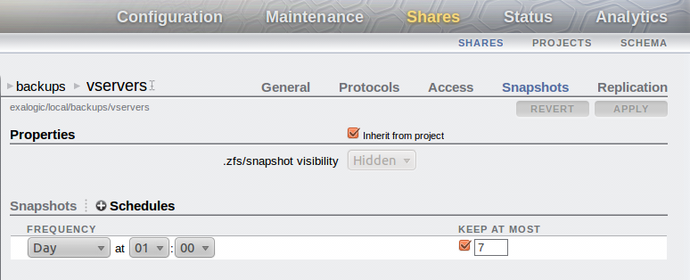
The first activity is to create a project/share to hold the backups of the vServers. Once the filesystem has been created then ensure that you setup the system to automatically create regular snapshots of the share. In the graphic below the share has been setup to snapshot the system daily at 1am and to keep 1 week's worth of snapshots on the storage appliance.


You should also setup replication to push the backups to a remote location for safekeeping. This is a simple activity of setting up a replication target under the Configuration/Services/Remote Replication tab then for the share (or at a project level) define the replication settings.
Make sure the share has root squash enabled. (root access in an NFS exception)

Mount the share on the vServer

It is now possible to mount the share on the vServer. This can be done dynamically at the point in time when the backup is performed or via a permanently mounted share.
It is necessary to mount the share using NFS v3. This is because there are a number of specialist users that will be setup on the vServer with ownership of certain filesystems. (eg. the ldap user) Because NFS v4 has a user based security check then these files may fail to backup successfully so NFS v3 is a better bet.

If using a permanent mount point defined in /etc/fstab then there should be a line similar to that shown below.
...
<IP/Host of storage appliance>:/export/backups/vservers /u02/backups nfs rw,bg,hard,nointr,rsize=131072,wsize=131072,tcp,vers=3 0 0
...

However general advise would be to mount the share specifically for the backup then umount it so that under normal usage of the vServer the backup is not visible to users of the system. This is the mechanism that the linked script uses.

On an Exalogic the initial backup of a simple vServer that has nothing but a deployment of WebLogic took just over 6 minutes for the first backup. Subsequent backups make use of the intelligence built into rsync to only copy changes to the backup version, thus following copies were completed in ~30 seconds. Obviously if there had been a lot of changes to the files then this number would increase towards the original 6 minutes.

vServer configuration for backing up

rsync is a fairly simple command to use, however the setup required to ensure it is configured to copy the correct files to an appropriate remote location is more complex. The basic command to use is shown below with the restore being a reversal of the command.

# rsync -avr --delete --delete-excluded --exclude-from=<List of files to exclude> <Backup from> <backup to>

However to simplify the setup I have created a short script that makes use of the Exalogic ZFS appliance and excludes files appropriate for the Oracle Linux base image. The script I used can be found here and its usage is shown below
donald@esat-df-001 :~/consulting/oracle/exalogic/bin/backup/rsync$ ./rsync_backup-v1.0.sh -help
rsync_otd_backup.sh 
-action=(backup|restore) : [backup]
-nfs_server=<IP of NFS storage device> : [nfs-server]
-nfs_share_dir=<Directory of NFS share> : [/export/backups/vservers]
-mount_point=<Directory of mount point on local machine> : [/mnt/backups]
-backup_dir=<root directory for backups under the mount point> : [esat-df-001]
-directory_to_backup=<Source directory for backing up.> : [/]
-automount
-script

If automount is not specified the system will assume that the mount point defined already exists
-script is used to indicate that the script is run automatically and should not prompt the user
for any input.

Each parameter can be defined from the command line to determine the configuration, however if called automatically (from cron for example) you must include the -script option, otherwise it will prompt for confirmation that the configuration is correct.  The defaults are all setup within the script itself, inside the setup_default_values function at the top, these should be changed to suit your environment.  Similarly the function create_exclusion_list contains a list of files/directories that will not be backedup/restored.  Primarily because these directories are specific to devices attaches, temporary or cache files. The list here is what I have found works using Oracle Linux 5.6 but will need to be reviewed for your environment.
To perform the backup the simplest approach is to setup cron to run the job. I was using a backup run hourly, with the ZFS appliance keeping a copy on a daily basis but the specific needs for backup frequency will vary from environment to environment. An example of the crontab file used is shown below.
[root@esat-df-001 ~]# crontab -l
10 * * * * ./rsync_backup.sh -action=backup -script -nfs_server=172.17.0.17 -nfs_share_dir=/export/backups/vservers -mount_point=/mnt/backups -backup_dir=esat-df-001 -directory_to_backup=/
[root@esat-df-001 ~]#


Restore using rsync

The restore process is approximately a reverse of the backup process however there are various options that make this approach flexible. These being:-
  1. The ability to restore individual files or filesystems to the vServer
  2. A complete restore from backup of vServer
  3. The recreation of a vServer on another host/rack, restoring to the values defined in the backup.
These options can all be fulfilled by the use of rsync with varying degrees of manual intervention or different restore commands.

Recreating a vServer and restoring from backup

Should a vServer become corrupt or deleted (deliberately or accidentally) then it may be necessary to recreate the vServer from a backup. Assuming that the vServer is to have at least its public IP address identical to the previous server then the first activity is to allocate the same IP address to the new vServer that is will be created. This is done by simply allocating the IP address and then during the vServer creation process defining the network to have a static IP address.


Ensure that the vServer you create has a similar disk partitioning structure to the original. Perfectly OK for the partitioning to be done differently but it will be necessary to make changes to the backed up /etc/fstab file to match the new vServer layout and to perform the file system creation and same mount points.
Thus the activities to perform/consider on creation are:-
  1. Ensure the disk size/additional volumes are created as needed.
  2. Allocate IP address for any IPs that are to be recreated in the new vServer. Statically assign them to the vServer during creation.
  3. After first boot
    1. Format and mount volumes/additional disk space as needed.
    2. For all the NFS mounts that were on the previous vServer re-create the mount points. (All defined in the backup copy of /etc/fstab)
    3. Ensure disk partitions/volumes are mounted such that the vServer has similar storage facilities to the original.
  4. Restore from backup.
  5. Edit files to correct for new environment
    1. Edit /etc/hosts to make changes as necessary to any IP addresses appropriate to new vServer/environment
    2. Check the /etc/fstab file to correct according to new partitioning/volumes attached if changed from original
  6. Reboot & test
Point 4 is where the rsync command is run to create a backup, if you are wanting to backup to one of the earlier snapshots then make sure that you use the ZFS appliance to create a new share from one of the snapshots and then use that share to mount the backup and copy the files onto the new vServer.

Backup by Templating an existing vServer (A later blog post....)


Monday, 10 September 2012

Setting up a local Yum Server using the Exalogic ZFS Storage Appliance

One of the Exalogic Racks that I have setup had no access to the internet from the 10GbE network, as such no easy mechanism for additional rpms to be deployed to the vServers that are created.  In order to make things simpler for installation on the multiple vServers and have some degree of control over what versions of the software are installed this note describes how to setup a local yum server.
Within an Exalogic we have a handy HTTP server built into the ZFS storage device which we will use to serve up the content of the YUM Repository. This makes it available to every vServer that is attached to the vServer-shared-storage network.

Setup the Yum Repository

This first activity is to setup the actual repository on the shared repository. A few activities are required to enable this:-

Create a share for the repository

The first step is to create a share on the Exalogic rack that will be used to host the yum repository and make it available via HTTP. Some instructions on setting up a share can be found in the technote "Creating a Project or Share in the ZFS appliance".  In this case this service will be common to all vServers so use the existing project "common" and create a share under it called "yum-repo", making the share available via HTTP.

Having created the share we need to make it available via HTTP. To achieve this firstly enable the HTTP service on the ZFS appliance. This is achieved by clicking the enable icon on the HTTP service inside the Configuration/Services tab. The service shown below.


Having enabled the HTTP service it is then necessary to change the configuration for the share to make the share content available via HTTP. This is achieved by selecting "Shares" then picking the share itself. In our case this is common/yum-repo. Now select the Protocol tab option and set the "Share mode" of the HTTP service to Read Only.  If this is not possible it is probably because it has been set to Inherit from project.  If you are happy to have all shares under the project exposing their content via HTTP then leave the "Inherit from project" option selected and change the HTTP protocol on the project level so that it is set to Read only.  If you only want to expose this share then de-select the "Inherit from project" option and set the share mode to Read only.

Create the Repository

The simplest way to get a hold of the appropriate packages is to download the Exalogic base image. This is the .iso file rather than the virtual image which is a single image file as oppose to an installation CD. From the Exalogic e-delivery website it is possible to download the latest physical image. (At the time of writing this was the 2.0.0.0.0 version.) It ships as two zip files which need to be expanded and the runMe.sh run which will amalgamate the two images to create a single iso file.

Using the single iso file loopback mount the iso and then copy all the content onto the yum-repo share.

So an example process from a compute node to mount the iso and copy the contents off it is shown below.


# mkdir /mnt/yum-repo
# mount <IP address of shared storage>:/export/common/yum-repo /mnt/yum-repo
# cp <Path to base image>/el_x2-2_baseimage_linux_2.0.0.0.0_64.iso /mnt/yum-repo
# mkdir /mnt/yum-repo/tmp
# mount -o loop /mnt/yum-repo/el_x2-2_baseimage_linux_2.0.0.0.0_64.iso /mnt/yum-repo/tmp
# mkdir /mnt/yum-repo/el_x2-2_baseimage_linux_2.0.0.0.0_64
# cp -r /mnt/yum-repo/tmp/* /mnt/yum-repo/el_x2-2_baseimage_linux_2.0.0.0.0_64


Now we want to run the createrepo command to actually create the repository that all the clients can utilise. In order to achieve this the first thing we need to do is actually install the repository package, then run the createrepo command.

# cd /mnt/yum-repo/el_x2-2_baseimage_linux_2.0.0.0.0_64
# find . -name createrepo*
./Server/createrepo-0.4.11-3.el5.noarch.rpm
# rpm -ivh /mnt/yum-repo/el_x2-2_baseimage_linux_2.0.0.0.0_64/Server/createrepo-0.4.11-3.el5.noarch.rpm
warning: /mnt/yum-repo/el_x2-2_baseimage_linux_2.0.0.0.0_64/Server/createrepo-0.4.11-3.el5.noarch.rpm: Header V3 DSA signature: NOKEY, key ID 1e5e0159
Preparing... ########################################### [100%]
1:createrepo ########################################### [100%]
#
# createrepo .
3338/3338 - VT/etherboot-roms-kvm-5.4.4-13.el5.x86_64.rpm 6_64.rpm.rpmpm
Saving Primary metadata
Saving file lists metadata
Saving other metadata
#

Configure the Client & Install the Packages.

Now log onto your vServer to configure the yum repository. This is done by creating the file /etc/yum.repos.d/local_yum.repo, the content of which specifies the HTTP address for the yum repository on the shared storage. Once created you can run yum reposlist to ensure that it is configured correctly.yum

# cat /etc/yum.repos.d/local_yum.repo
[local_yum]
name=Exalogic TVP yum rack
baseurl=http://<IP address of your ZFS Storage appliance on the vServer-shared-storage network (172.17.0.n by default)>/shares/export/common/yum-repo/el_x2-2_baseimage_linux_2.0.0.0.0_64
gpgcheck=0
enabled=1

#
# yum repolist
Loaded plugins: rhnplugin, security
This system is not registered with ULN.
ULN support will be disabled.
local_yum | 951 B 00:00
local_yum/primary | 1.6 MB 00:00
local_yum 3338/3338
repo id repo name status
local_yum Exalogic TVP yum rack enabled: 3,338
repolist: 3,338
[root@esat-ldap ~]#

#

Then run 'yum repolist' and if everything's is ok you see the repository listed.

Friday, 7 September 2012

Creating a project/share on the Oracle ZFS Storage Appliance

To quote from a colleague - a tea break snippet (See The Old Toxophilist) on setting up a project and share using the ZFS Storage Appliance that is part of the Exalogic rack.

If you are doing this through the Browser User Interface (BUI) then the first thing to do is point your browser at the management administration interface for the ZFS Storage appliance on port 215. Connecting to the active storage head.

https://<IP of active storage head>:215/

Log on to the service and navigate to the shares tab then pick the Projects sub-tab.
You can then click on the small + symbol beside the Projects title, as shown below.


Give your project a suitable name, say MyProject. You can now select this project from the Projects page to edit it. This is done by highlighting the MyProject line and clicking the pencil icon to edit it. Now we want to do some basic best practice configuration.
  1. Click on the General tab and specify the "Mountpoint" to be /export/<project name> This will mean that all the data and shares held in this project will be contained within a single directory structure on the storage device. The rest of the General settings can be left at the defaults in the first place.
    eg. /export/myproject  (Minor unix standard to use lower case characters, if you do use mixed, bear in mind it is case sensitive.)
  2. Click onto the Protocol tab.
    1. Set the Share Mode to be None. This stops anyone but the nodes that are specifically defined connecting to the share.
    2. Click on the + symbol beside the "NFS Exceptions" to add an exception. I tend to use the Type of "Network" and define a network/netmask as the Entity to specify which compute nodes/vServers can access the share. In a virtualised Exalogic the default vServer shared storage network is 172.17.0.0/16 so giving these read/write access is the norm. There is also a tick box for "Root Access", this defines what is known as root squash which determines if the root user of a connected client has root access to the files in the share. Unless specifically needed this should not be enabled.
    3. Add additional networks as needed for your environment.
    4. HTTP - if you require access to the shares via an HTTP interface then set the share mode for this protocol to be read only.
    5. Replication - No need for this in a very simple test environment but for all other environements the Replication tab allows you to define backup locations for the share.
  3. Click on the Shares tab
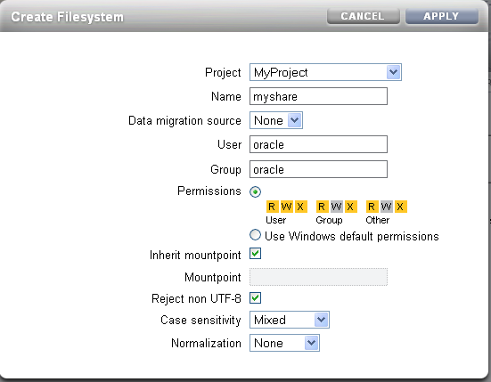
    1. For each share you wish to create click on the + symbol beside the Filesystems, give your share a name. The other options such as the User and Group and permissions are really dependent on what the needs of your environment are. In the example shown below the assumption is that the share myshare will be mountable from /export/myproject/myshare (the default), and once mounted will show up as being owned by oracle:oracle.
      Note :- you may find that the appliance objects to the owner of oracle:oracle as an unknown user and group. If you are just using NFSv3 then you can enter the ID for the oracle user in here which will transfer over to the client server. If using NFSv4 then the user must exist in the shared authentication location - LDAP or NIS.


Now all you need do is mount this share from a compute node (Physical Exalogic) or vServer (virtual Exalogic)
# mount <ip of storage>:/export/myproject/myshare /mnt

or if you want it to be auto-mounted on boot add it to the /etc/fstab file on a directory such as /u01.

Tuesday, 31 July 2012

Limiting User Access with LDAP Authentication to Multiple Servers [part 4 of 4]

This technote is the last in a line of notes about using LDAP to provide a shared authentication facility, using the components of an Exalogic.

Introduction

In the earlier posts in the series
  1. Using LDAP for Shared Authentication.
  2. Securing OpenLDAP Communications
  3. Configuring OpenLDAP for High Availability. (Master/Slave or Provider/Consumer configuration)
we considered how to setup a directory server and configure the ZFS Storage Appliance and OEL instances to use this for authentication.  We then took the next step to secure the communications by encryption and finally changed the LDAP setup so that we can have multiple copies running to make the system tolerant to failures.

As described we have a mechanism of deploying  a shared authentication that can be used by the storage and multiple compute nodes.  This does not cover the use case of enabling a user to log onto some compute nodes but not others.  To achieve this we need to think about adding some selectivity to the authentication.  There are many ways to achieve this, one approach would be to use Access Control Lists and dynamically build up exactly what servers any particular user might have access to - this may be the subject of a future post.  The simplest way that may achieve what we are looking for is to simply use the LDAP tree structure to define what users can be authenticated to a particular host.

A default directory, for authentication purposes, consists of a tree structure something like:-
  • Base DN (dc=example,dc=com)
    • ou=Group
      • cn=adm
      • cn=audio
      • cn=...
      • cn=users
      • cn=<your group>
      • ...
    • ou=Hosts
    • ....
    • ou=People
      • uid=adm
      • uid=avahi
      • ...
      • uid=<your user>
    • ...
In this tree structure the key entries are under ou=Group and ou=People where the users of your system will reside.  The "People" entry holding the users password, home directory, group, user identifier etc.

Reconfiguring the Directory to introduce new branches.

By creating an additional tree structure it is possible to group users and groups together and then set different servers to perform their search under these different structures.

For example, we might have 8 servers in the lower half of an Exalogic half rack being used for one department (sales) and the upper 8 servers by another department (finance)  With this a structure might look like:-
  • Base DN (dc=example,dc=com)
    • ou=Group
      • cn=adm
      • cn=audio
      • ...
    • ou=Hosts
    • ....
    • ou=People
      • uid=adm
      • uid=avahi
      • ...
    • ...
    • ou=departments
      • ou=sales
        • ou=Group
          • cn=sales
        • ou=People
          • uid=salesman01
          • uid=salesman02
          • uid=salesmanager
      • ou=finance
        • ou=Group
          • cn=finance
        • ou=People 
          • uid=accountant01
          • uid=accountant02
          • uid=financedirector

Compute Node configuration

On the client machines the only change we need to make is in the /etc/ldap.conf file, changing the Base DN entry.  So for the lower 8 compute nodes we would have an ldap.conf file that looks like:-

...
host 192.168.23.105

# The distinguished name of the search base.
# base dc=vbel,dc=com
base ou=sales,ou=departments,dc=vbel,dc=com

# Another way to specify your LDAP server is to provide an
# uri with the server name. This allows to use
# Unix Domain Sockets to connect to a local LDAP Server.
#uri ldap://127.0.0.1/
...

where the example base DN for the directory is dc=vbel,dc=com.

For the upper 8 compute nodes make the same change to the ldap.conf file but set the organisational unit to be finance.

...
base ou=finance,ou=departments,dc=vbel,dc=com
...


ZFS Storage Appliance Configuration

Things are slightly more complex on the ZFS storage.  Because this is a shared resource it has to be able to see all the users for all the departments.  In order to configure this there are a couple of settings required on the LDAP service configuration. 


In the example above we need to ensure that the "Base search DN" is set to the base DN of our directory server and that the "Search Scope" is set to subtree (recursive).  This means that the storage will search for users down all the branches from the Base Search DN.

By default the storage appliance will start the search from "ou=People, <Base DN>" in our example we have our departmental users under "ou=departments,<Base DN>" which does not match the default appliance search path.  To fix this we need to "Edit" the "Schema Definition".  Clicking the Edit... link brings up an additon options box to fill in.


In this simple window add the Base DN as the Search Descriptor for both Users and Groups, press save and apply the changes to the LDAP service.


Now check that you can log onto the lower 8 compute nodes as one of the sales users but not as a finance user and vice versa for the upper 8 compute nodes.

Gotcha's and Limitations

This approach is great because it is simple but it is important to understand some of the limitations.  Firstly, make sure that the same user does not exist under different branches this could lead to confusion as the storage might recognise the user under one branch while the compute node picks the user from the other branch.